The global manufacturing sector relies heavily on high-precision tooling to produce durable, high-quality component parts. Whether you are launching a complex medical device, or a consumer electronic housing, knowing how to make injection molds is vital for optimizing unit cost, ensuring dimensional accuracy, and accelerating market entry.
At Rally Plastic, we have spent decades perfecting the custom tooling lifecycle. Modern plastic injection molding demands an exceptional blend of advanced digital engineering, metallurgical science, and micro-tolerance CNC machining. This ultimate technical guide walks you step-by-step through the entire plastic mold manufacturing pipeline—from initial CAD development and material selection to high-precision machining, T0 trial validation, and ongoing mold maintenance.
Understanding the Plastic Injection Mold: Core Components & Function
Before exploring the manufacturing steps of how to make injection molds, it is helpful to clarify what an injection tool consists of. A custom mold is a precision-engineered steel or aluminum structure designed to receive melted resin under extreme hydraulic pressure, cool it rapidly, and eject the finished part without visual defects.
Let’s break down how a custom tool actually operates in practice. The process starts when the two primary halves, known as the core and the cavity, clamp together under massive machine tonnage. The cavity is responsible for forming the exterior cosmetic shape of your component, while the core dictates the internal geometry and hidden structural features. Once clamped, they create a highly pressurized hollow volume. To get the molten liquid into this space, the machine injects plastic through the runner and gating system. This network acts as the highway for the hot polymer, channeling it from the machine’s nozzle directly into the part details. Depending on your budget and production volume, this might be a simple cold runner or a highly energy-efficient hot runner system.
As the plastic fills the void, it needs to be cooled rapidly to solidify. This is achieved via strategic cooling channels—a complex internal plumbing network engineered to circulate temperature-controlled water or oil, pulling heat away from the plastic to enable uniform thermal dissipation. Finally, once the part is solid, the mold opens, and the ejection mechanism takes over. Carefully placed ejector pins, stripper plates, or air-blast valves activate to push the finished component safely clear of the tool, ready for the next cycle.
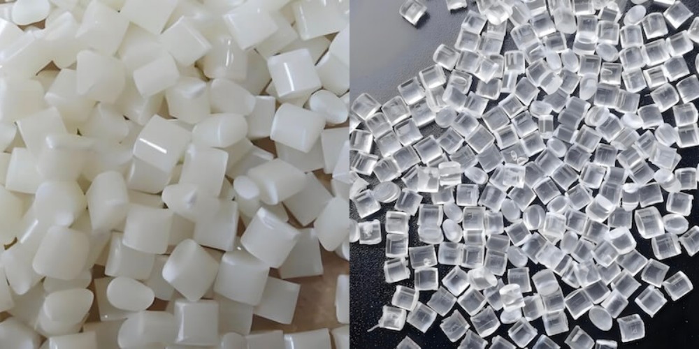
Understanding these internal dynamics is key when evaluating plastic injection mold applications across industries such as aerospace, medical equipment, and telecommunications. Using the appropriate tool design ensures that the raw injection molding plastic flows smoothly without premature freezing, yielding consistent parts across millions of cycles during mass injection molding.
Phase 1 – Plastic Injection Mold Design and Engineering Considerations
Superior tooling begins long before any metal cutting occurs. Proper injection mold design sets the foundation for structural integrity, minimal cycle times, and smooth production runs.
Plastic Injection Mold Design Workflow
- Part Geometry & DFM Analysis (Draft angles, wall thickness, gate)
- Mold Flow Simulation (Filling pattern, shrinkage, sink marks)
- 3D CAD / 2D CAM Engineering (Core/Cavity layout, cooling channels)
- Toolpath Generation & Validation (CNC code, EDM electrode design)
Design for Manufacturability (DFM)
Our engineering team at Rally Plastic conducts an exhaustive Design for Manufacturability (DFM) review on every incoming 3D CAD model. Key design parameters include:
Draft Angles: Adding a 1° to 2° taper per side allows easy part release and prevents drag marks.
Wall Thickness Uniformity: Maintaining consistent nominal wall thickness prevents internal voids, sink marks, and structural warpage.
Gate Placement: Strategic gate positioning minimizes visible seam lines, optimizes fill balance, and reduces cosmetic defects.
Mold Flow Analysis & Multi-Cavity Precision
Using sophisticated Computer-Aided Engineering (CAE) software, engineers simulate fluid dynamics, thermal dissipation, and plastic shrinkage. If you are exploring how to make injection molds for custom plastic products, pre-production simulation is indispensable. It allows engineers to balance filling pressures, optimize cooling channels, and resolve complex issues such as avoiding parting line mismatch in multi-cavity custom molds.
Through careful upfront planning, custom plastic injection molding projects avoid costly steel modifications down the road, ensuring long-term tooling reliability and predictable part dimensions.
Phase 2 – Selecting Injection Mold Materials: Tooling Steels vs. Aluminum
Selecting appropriate injection mold materials dictates your tool’s lifespan, thermal performance, and overall production economics. Tooling metals generally fall into two broad categories: aluminum alloys and hardened steel alloys, each serving a very specific production strategy.
For rapid prototyping and low-volume production runs (typically 1,000 to 10,000 parts), aluminum tooling, such as QC-10 or 7075-T6, is often ideal. Aluminum offers exceptional heat transfer, which allows for incredibly fast cooling times and shorter cycles. However, its softer nature means it lacks the physical wear resistance needed for abrasive, glass-filled resins.
On the other hand, pre-hardened steels like P20 or NAK80 are excellent for mid-volume commercial production, easily handling up to 500,000 cycles by balancing good machinability with decent surface polishability. For ultra-high-volume production exceeding a million cycles, fully hardened tooling steels like H13 or S136 represent the gold standard. S136 stainless steel, in particular, provides superior corrosion resistance. This is absolutely critical when working with aggressive or halogenated polymers (like PVC) that would otherwise pit and destroy a softer mold face over time.
| Steel Grade | Hardness (HRC) | Thermal Conductivity | Best Use Case Application |
| Aluminum 7075 | 15–20 | Very High | Rapid prototyping & low volume |
| P20 Steel | 28–32 | Medium | General commercial production |
| H13 Steel | 48–52 | Medium-Low | High temp & long production runs |
| S136 Stainless | 48–54 | Medium | High cosmetic clarity & corrosive resin |
When selecting the best steel for high volume plastic injection mold projects, engineers must also consider the specific plastic for injection molding being utilized. Corrosive polymers like PVC or abrasive glass-filled nylons quickly degrade softer metals, making hardened stainless steel or specialized protective tool coatings essential.
Phase 3 – Plastic Injection Mold Manufacturing: CNC Machining and EDM
Once engineering designs and material specs are finalized, physical plastic injection mold manufacturing begins. This crucial step in how to make injection molds transforms raw metal blocks into ultra-precise core and cavity inserts.
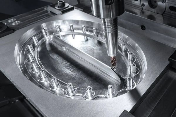
Computer Numerical Control (CNC) milling machines are first used to remove the bulk of raw steel stock. High-speed 3-axis and 5-axis CNC equipment cut outer mold bases, ejector housing pockets, and main cavity contours to within tight micro-scale tolerances.
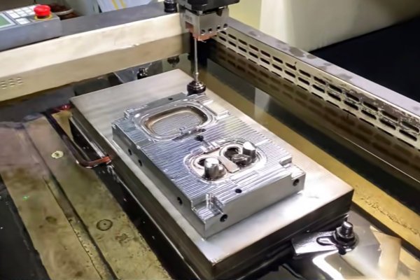
However, certain intricate geometric features simply cannot be cut using rotating CNC milling bits, no matter how small they are. Features like sharp internal corners, deep narrow ribs, or fine knurled textures require a completely different approach. In these scenarios, toolmakers employ Electrical Discharge Machining (EDM). The most common method is Sinker EDM, which uses custom-machined copper or graphite electrodes to literally burn intricate shapes into the hardened steel using controlled electrical spark erosion. For cutting precise profiles straight through the steel plates—such as slide lifters, custom insert pockets, and ejector pin holes—Wire EDM is utilized. This process uses a continuously moving thin brass wire to slice through the metal with extreme, microscopic accuracy.
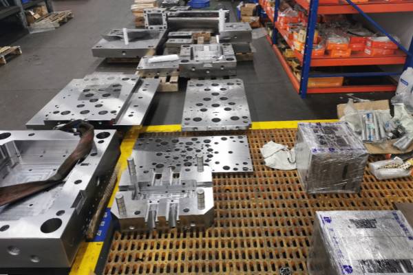
After machining, skilled toolmakers at Rally Plastic hand-polish the cavity surfaces to achieve the desired surface finish (ranging from SPI-D3 matte finishes to SPI-A1 optical mirror polishes). Chemical etching can also create custom leather, woodgrain, or geometric textures on the mold face. Finally, the finished cavity inserts, core blocks, guide pins, cooling manifolds, and ejector assemblies are meticulously fitted together into a heavy-duty steel mold base. The assembled plastic injection mold is now fully integrated and prepared to be mounted into a commercial injection molding machine.
Phase 4 – Mold Testing (T0 Trial), Quality Assurance, and Troubleshooting
The process of how to make injection molds is only complete once its real-world performance is verified on the factory floor. The first trial run, known as the T0 trial, validates the tool under real production conditions.
The T0 Trial Procedure
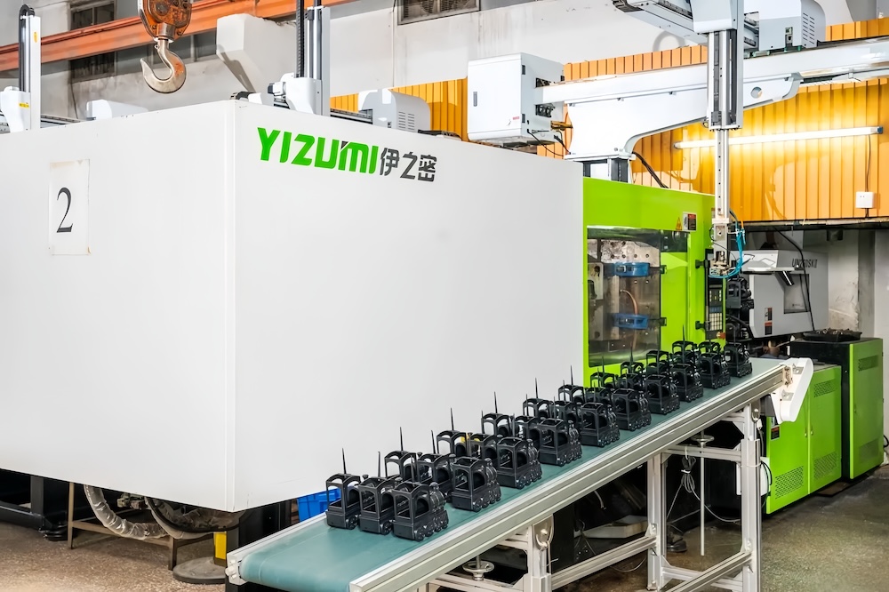
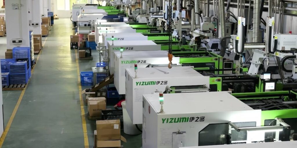
The tool is securely mounted into an industrial hydraulic or all-electric injection molding machine. Technicians connect water lines, verify clamp force settings, and heat the barrel to the plastic’s melt temperature.
T0 Trial & Testing
- Mount tool in injection molding machine
- Perform short-shot testing (verify fill balance)
- Apply full pressure and optimize cooling cycle
- Measure sample parts against CMM tolerances
- Perform tool modifications and tuning if required
During this initial injection molding process, engineers perform a series of “short shots.” They deliberately under-fill the cavity. This allows them to observe exactly how the molten plastic flows through the runner system. This visual test verifies balanced filling across all cavities before applying full pressure.
Once full parts are pressed, quality assurance teams conduct full dimensional scans. They use Coordinate Measuring Machines (CMM) and optical comparators. Minor defects are quite common during the T0 phase. Identifying them is exactly why this trial exists. For example, excess plastic can sometimes leak between the mold faces. This results in “flash.” The team must then tighten the parting line fitting or adjust the machine’s clamp tonnage.
Parts might also display “sink marks.” These are surface depressions caused by uneven wall cooling. To fix this, engineers adjust thermal parameters or modify the hold pressure. They might also recommend a structural rib redesign. Conversely, “short shots” occur when the cavity fails to fill completely. Low injection pressure, cold melt temperatures, or inadequate gas venting often cause this issue. Toolmakers must then expand the gates or clean out the vent paths. Following the sample inspection, the team makes minor adjustments to the steel or machine parameters. They repeat this process until the parts meet exact engineering specifications.
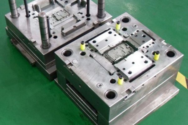
Mold and Maintaince Repair Services
A premium injection mold represents a major capital investment. Implementing systematic injection mold maintenance routines protects that investment, prevents unplanned downtime, and ensures consistent part quality across years of production.
Preventive Maintenance Protocols
Daily Bench Inspection: Wipe down parting lines with solvent, inspect ejector pins for wear, and apply rust inhibitors after production runs.
Periodic Deep Cleaning: Dismantle core and cavity inserts, clear mineral deposits from internal cooling channels, and replace worn O-rings.
Ultrasonic Cavity Cleaning: Remove burnt resin residue and gas buildup from venting slots without scratching polished steel faces.
Even with meticulous care, high-stress production environments lead to natural component wear. Partnering with a supplier that provides comprehensive injection mold repair services ensures your tool can be quickly re-conditioned through laser welding, re-machining, or insert replacement. Proper maintenance allows custom steel tooling to smoothly sustain millions of production cycles for demanding injection molding of plastics.
Why Partnering with the Right Plastic Injection Molding Companies Matters
Building a world-class injection tool requires deep metallurgy expertise, advanced multi-axis CNC technology, and seasoned engineering talent. Trying to cut corners with inexperienced toolmakers often leads to delayed product launches, flash defects, and premature mold failure.
Evaluating leading plastic injection molding companies requires looking beyond basic unit pricing. You need a trusted partner capable of offering comprehensive end-to-end tooling capabilities:
-
In-house engineering, DFM analysis, and mold flow simulation.
-
State-of-the-art multi-axis CNC, Wire EDM, and mirror-polishing equipment.
-
Strict CMM quality inspections and T0/T1 trial support.
-
Comprehensive preventive tool maintenance and lifetime mold guarantees.
At Rally Plastic, we deliver tailored injection molding services that align with your exact engineering specifications and budget requirements. Help you transition seamlessly from initial concept to high-volume manufacturing.
Conclusion
Mastering how to make injection molds is a detailed engineering process that combines advanced software design, expert metallurgy, precision CNC machining, and thorough quality testing. Every step—from initial draft angle adjustments to final T0 trial parameters—directly influences part quality and production efficiency.
Whether you need a rapid aluminum prototype tool or a multi-cavity hardened steel mold for mass production, working with an experienced custom plastic injection mold maker ensures long-term success.
Ready to bring your next product concept to life? Contact Rally Plastic’s team today to get a custom mold quote and discover how our advanced tooling solutions can optimize your manufacturing workflow.