Designing high-quality plastic parts requires attention to many small but critical details. One such detail is the parting line in injection molding, often overlooked until it causes cosmetic or functional issues. When improperly placed or poorly managed, parting lines can lead to surface defects, poor sealing, and even mold misalignment. These issues not only affect product quality but also increase production costs and rework. Understanding the function and impact of the parting line helps engineers make smarter design choices. In this article, we’ll break down what the parting line is, why it matters, and how to control it effectively.
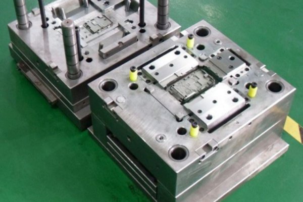
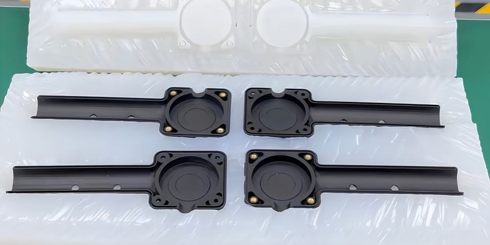
The parting line in injection molding is the visible seam on a molded part where the two halves of the mold meet. It marks the boundary between the “A-side” and “B-side” of the mold. This line forms naturally during the molding process and is essential for part ejection. Parting lines vary in location depending on the part’s geometry and mold design. While they are a normal result of injection molding, their placement and quality must be carefully controlled to avoid defects and ensure proper fit, appearance, and functionality.
Definition and Function of the Parting Line

The parting line in injection molding is the visible line or seam formed where the two halves of a mold—commonly referred to as the core and cavity—come together. This line appears on the molded part as a result of the mold’s split and is an unavoidable outcome of the molding process.
Mold halves must tightly close to contain the molten plastic during injection. However, even with precision alignment, a fine line forms at the interface. This parting line defines the boundary where the mold opens and the part is ejected.
In most designs, the parting line is placed along a natural edge or non-cosmetic surface. Its location influences part appearance, mold complexity, and ease of demolding. A well-positioned parting line minimizes flash, improves functionality, and reduces post-processing work.
Understanding this concept early in the design phase is critical for producing high-quality injection molded parts.
Why the Parting Line Matters in Injection Molding

Although often subtle, the parting line in injection molding plays a critical role in product performance and appearance. Visually, it can leave a noticeable seam on the finished part, which may require secondary processing such as trimming or sanding—especially for consumer-facing or cosmetic components. A poorly positioned parting line can reduce product appeal or signal low manufacturing quality.
Functionally, the parting line can interfere with sealing surfaces in applications requiring airtight or watertight enclosures. For example, in housings for electronics or medical devices, even a small mismatch or flash along the parting line can compromise IP ratings and functional integrity.
From a manufacturing perspective, the parting line affects mold design complexity and part consistency. A strategically placed line ensures easy mold release and reduces the chance of flash or misalignment. In contrast, awkward line placement may complicate tooling, increase wear, and lead to tolerance issues across production runs.
In short, managing the parting line is essential for visual quality, functional performance, and process efficiency in plastic injection molding.
Common Locations of the Parting Line

The placement of the parting line in injection molding depends heavily on the part’s geometry, function, and aesthetic requirements. Mold designers aim to position the parting line where it is least visible, easiest to manufacture, and causes minimal interference with function or appearance.
Flat surfaces and midlines are among the most common choices. For symmetrical parts, the parting line often follows the centerline, ensuring balance and simplifying mold construction. In simple box-type housings or rectangular components, the line usually runs along the sidewall or base edges.
Contour-based parting lines are used when the part has a complex shape or non-planar profile. These lines follow the natural geometry of the part, ensuring better flow, fewer undercuts, and easier mold release. However, they may be more challenging to machine and align precisely.
For example, in electronic enclosures, the parting line typically runs along the bottom edge or back side. In circular connectors, the line may wrap around the circumference at a neutral zone. For small precision parts, the line is often positioned to avoid functional faces or mating surfaces.
To determine the optimal parting line location, designers evaluate:
-
Draft angles and ejection direction
-
Surface visibility and cosmetic zones
-
Assembly or sealing interfaces
A well-placed parting line balances manufacturing feasibility, visual impact, and product functionality.
How Mold Designers Determine the Parting Line

Determining the parting line in injection molding is a strategic decision that balances manufacturing feasibility, visual quality, and product performance. Mold designers begin by analyzing the ejection direction—the direction in which the part will be removed from the mold. This step helps identify surfaces that require draft angles and areas that could complicate demolding if the line is poorly placed.
The geometry of the part heavily influences parting line placement. Designers assess sharp corners, undercuts, and functional features to ensure smooth mold release and minimal tool complexity. Complex geometries may require stepped or contoured parting lines to follow the part’s shape.
One common strategy is to hide the parting line along non-cosmetic or less visible surfaces. For example, designers may align the line with an edge, corner, or underside of a part. This approach reduces the need for post-processing and improves the perceived quality of the final product.
Importantly, Design for Manufacturability (DFM) principles guide this decision-making. DFM involves evaluating the part for ease of tooling, minimizing flash, and avoiding costly rework. During the DFM stage, both the part and the mold are optimized to ensure that the parting line supports fast production, low defect rates, and efficient assembly.
Ultimately, an experienced designer integrates aesthetics, function, and manufacturability to define the most suitable parting line location.
Challenges and Defects Related to the Parting Line

While the parting line in injection molding is a necessary feature, it can also introduce several common defects if not properly managed. Among the most frequent issues is flash, also known as burrs—thin excess material that escapes between the mold halves. Flash typically forms due to poor mold alignment, excessive injection pressure, or worn tooling.
Misalignment is another concern. If the mold halves are not perfectly aligned, the parting line will shift, creating an uneven or stepped seam. This not only impacts the appearance but can also affect assembly fit or sealing in precision components.
In some cases, the parting line can create visible surface inconsistencies or rough textures, especially if mold temperature is not uniform or the tool surfaces are damaged.
To address these problems, manufacturers must prioritize mold maintenance and quality control. Regular inspection of mold surfaces, clamping systems, and alignment pins helps prevent flash and misalignment. Proper temperature regulation and cycle time optimization also contribute to consistent parting line quality.
Additionally, using high-quality mold steel and applying surface treatments can reduce wear and extend tool life. By actively managing these factors, manufacturers can minimize parting line defects and maintain product integrity across production runs.
Best Practices to Manage Parting Lines

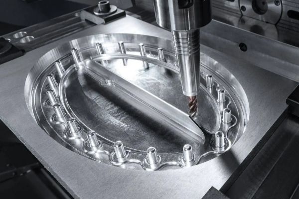
Effectively managing the parting line in injection molding requires both precise mold design and ongoing process control. One of the most critical factors is high machining accuracy during mold fabrication. CNC machining and EDM should be used to ensure that both mold halves align perfectly with minimal tolerance deviation.
Selecting the right mold steel also plays a key role. High-hardness, wear-resistant steels like H13 or S136, combined with surface treatments such as nitriding or polishing, help maintain edge integrity and minimize flash over extended production cycles.
During production, it’s essential to conduct routine inspection and maintenance. Checking for alignment wear, cleaning the sealing surfaces, and monitoring clamp force settings ensures long-term mold reliability. If left unchecked, even minor deviations can lead to parting line shift or flash formation.
Additionally, temperature control systems should be regularly calibrated to prevent uneven expansion or thermal stress that can affect mold fit. Real-time quality checks—especially for high-precision or cosmetic parts—allow quick identification of flash or misalignment issues.
By applying these best practices, manufacturers can ensure consistent part quality, minimal rework, and longer mold life, even in demanding production environments.
Conclusion
The parting line in injection molding is more than a cosmetic detail—it directly impacts product functionality, appearance, and manufacturability. Poorly managed parting lines can lead to flash, misalignment, and sealing failures. That’s why thoughtful planning at the design stage is essential.
By considering mold direction, part geometry, and manufacturing limitations early on, engineers can avoid costly rework and ensure consistent, high-quality results. A well-placed parting line simplifies mold construction, improves aesthetics, and supports better long-term production outcomes.
Ready to optimize your injection molded parts?
Upload your drawings or contact RALLY Plastic today to get expert support on mold design and custom injection molding solutions. We’ll help you achieve precision, performance, and production efficiency—every step of the way.